So far in this multi-part series on the MFOS Noise Toaster Lo-Fi Analog Synthesizer, we built and analyzed the Audio Amplifier, VCO, LFO, and AREG circuits. We were able to explore some neat frequency modulation effects by using the LFO and AREG to mess with the VCO Frequency. Now, let’s step this up a notch by adding a VCF or voltage-controlled filter circuit.
Be sure to check out the earlier posts in this series before reading this one for a complete understanding about how the various circuits work together.
What Is a VCF on a Synthesizer?
A VCF or Voltage Controlled Filter is a circuit that attenuates certain frequencies from a sound source. A control voltage can be applied to the VCF to dynamically change which frequencies are affected. Filters are an essential part of sound synthesis that allow us to shape the tonality or timbre of a sound by altering the harmonic content of the input audio signal. Essentially, a filter attenuates a certain range of frequencies. Soundwaves in the natural world and on synthesizers contain related “harmonics” in addition to the fundamental frequency. Harmonically rich signals can be filtered in various ways to sculpt, or shape sounds for a desired effect. Control voltages applied to the VCF can change the filtering effect dynamically to add rhythm and movement to the sound.
How the Noise Toaster VCF Circuit Works

The Noise Toaster VCF can take either the VCO’s ramp or square-wave outputs as an input. The WNS or white noise output can also be applied to the VCF input in addition to the VCO output. The VCF is a resonant low-pass type and can take either the LFO or ARG outputs as a modulation source.
2nd Order Active Low-Pass Filter
Take a look at the op-amp’s feedback loop in figure 1. You may recognize the RC network as a 2nd order RC high pass filter, or even two 1st order RC high pass filters connected back-to-back. Since an op-amp’s gain increases as the resistance in its feedback loop increases, the op-amp ends up acting as a low-pass filter.
Calculating Filter Cut-off Frequency
The cut-off control potentiometer R28 is connected as a variable resistor and is used to set the filter’s cut-off frequency. The cut-off frequency is the frequency at which the output is attenuated by 3dB and in this case is calculated by the equation below:
f = 1 / ((2π sqrt (R28 * R35 * C9 * C10)))This results in a cut-off frequency of around 238Hz with R28 cranked up or around 7.34kHz with R28 at 100 Ohms. The above assumes that R29 is all the way up and ignores the effect of Q8.
Resonance Control
An RC circuit has a tendency to cause oscillation when the input frequency matches the circuit’s resonant frequency. This frequency is determined by an equation similar to that for cut-off frequency:
fRes = 1/2πRCThe RC Circuit’s tendency to oscillate can be damped by adding resistance in series in the capacitance. This damping factor is called “Q”. A high Q RC circuit will have a greater tendency to oscillate. Q factor is determined by:
Q = XC/RWhere XC or capacitive reactance is:
XC = 1/2πfCResonance control pot R29 adjusts the circuit’s Q factor in the Noise Toaster ARG. When R29 is cranked up, it’s wiper shorts its resistive track thus increasing Q. This creates a cool “ringing” effect at a particular frequency.
JFET as Voltage Controlled Resistor

A JFET operated below the pinch-off region in its characteristics curves (figure 2) exhibits an ohmic relationship between its drain-source voltage and current. This makes the JFET act as a voltage controlled resistor. In the Noise Toaster, Q8’s drain-source junction is connected in parallel to the cut-off control R28. Mod source switch S6 is used to choose between the LFO or ARG as a modulation source. Mod Depth potentiometer R38 couples the CV signal from S6 to Q8’s gate via scaling and current limiting resistors R39 and R45. R44 and R45 bias the gate negative in relation to source.
Q8’s drain voltage and the CV input signal are fairly low. This results in Q8’s drain-source resistance varying linearly with the CV signal from either the LFO or the ARG. Q8’s varying resistance appears parallel to cut-off control R28 and changes the RC circuit’s effective resistance, thus modulating the filter’s cut-off frequency.
Building and Testing the Noise Toaster’s VCF
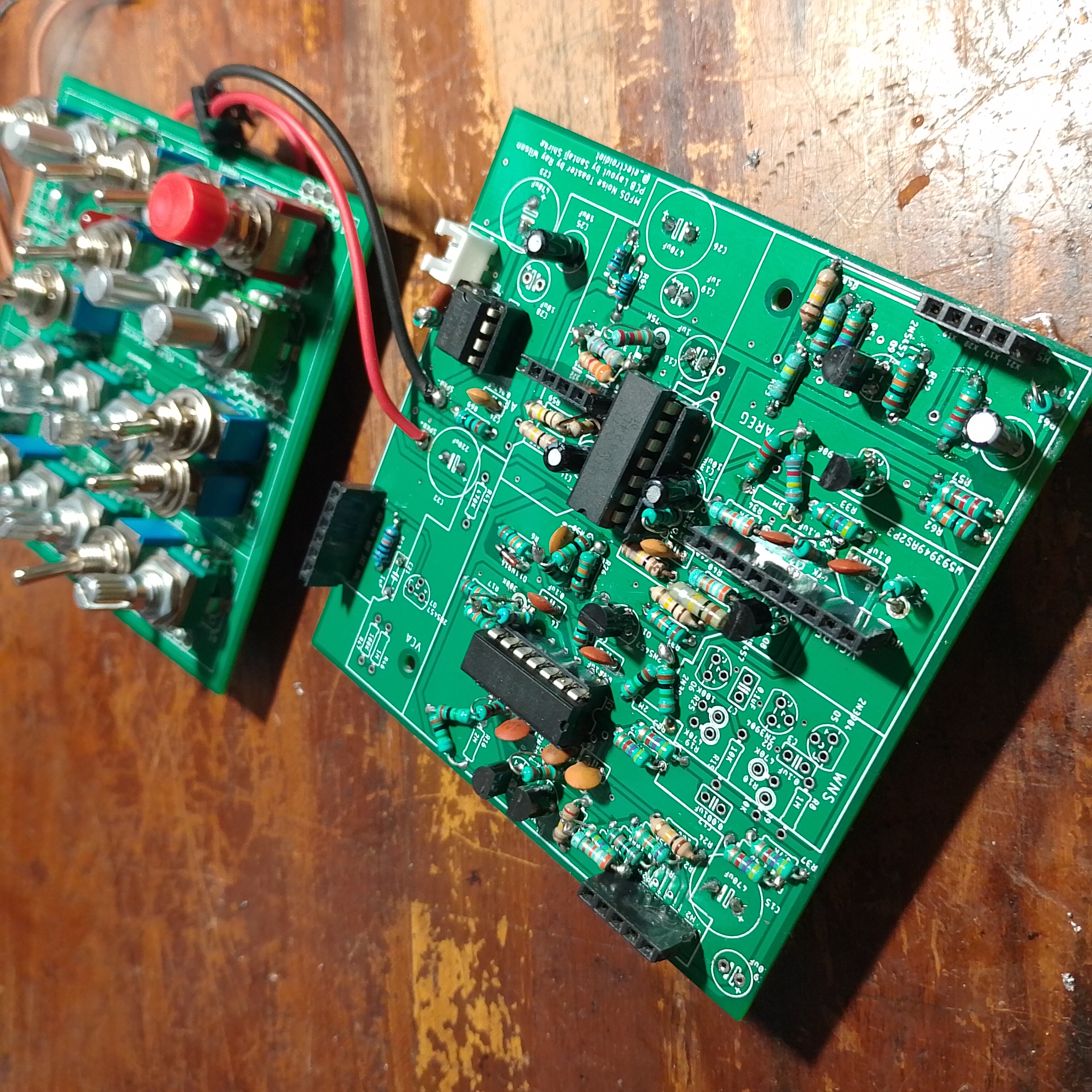
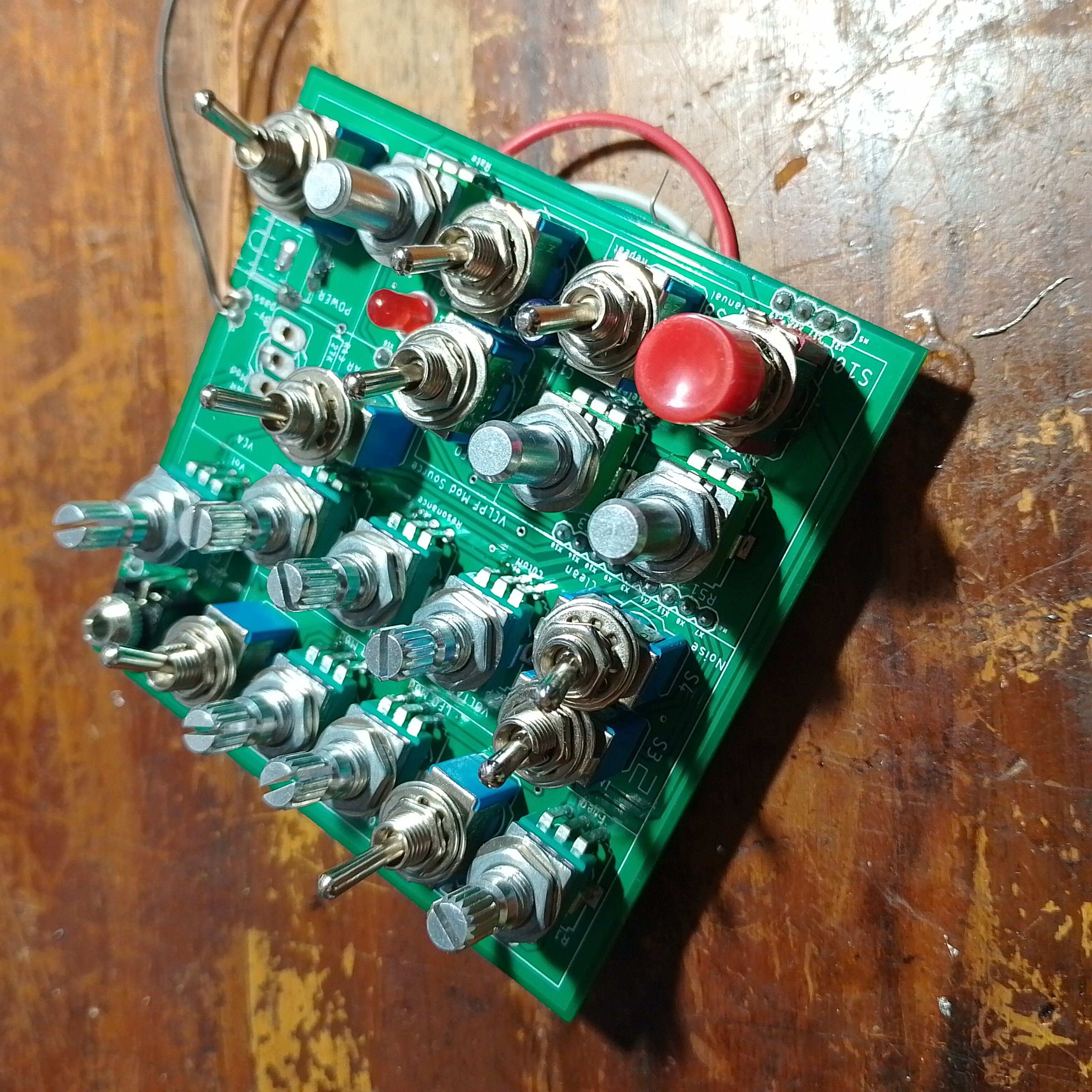
Adding the VCF opens up a new range of sounds we can make with our synth with more control over the harmonic content of the VCO output. Check out Part 1 of this series to learn more about my experimental sandwiched PCB design for the MFOS Noise Toaster. If you would like to build your own Noise Toaster, I recommend the official MFOS board or kit.

Build Your own Noise Toaster with Official MFOS PCBs and Kits…
In the next part, we’ll finish the circuit analysis and circuit construction by building the VCA and white noise generator. Follow @_electroidiot on Instagram to stay updated on my DIY electronics shenanigans and be sure to subscribe to my mailing list below to be notified of new posts.
Get Notified of New Posts, subscribe to the _electroidiot Mailing List.
Recommended Reading
Check out following resources to learn more about the MFOS Noise Toaster:
- Make: Analog Synthesizers by Ray Wilson.
- Official Noise Toaster page on the Music from Outer Space website.
- 2N5457 JFET datasheet by Motorola.
- “A guide to using FETs for voltage controlled circuits, Part 1” article EDN by Ron Quan.
- “Passive High Pass Filter” article on ElectronicsTutorials
Other Posts in this Series
- Noise Toaster Lo-Fi Synth Build and Analysis: Part 1 – Introduction
- Noise Toaster Lo-Fi Synth Build and Analysis: Part 2 – Power Supply and Audio Power Amplifier
- Noise Toaster Lo-Fi Synth Build and Analysis: Part 3 – CV Mixer, Expo. Converter, and VCO
- Noise Toaster Lo-Fi Synth Build and Analysis: Part 4 – Low Frequency Oscillator (LFO) Circuit Analysis
- Noise Toaster Lo-Fi Synth Build and Analysis: Part 5 – Attack Release Envelope Generator
Join the Conversation
If you notice any mistakes or errors, please feel free to let me know in the comments below.


Leave a Reply