Previously in this series of posts, we looked at the Noise Toaster Lo-Fi Analog Synth at a block diagram level and introduced the PCB layout and enclosure for the _electroidiot version of this classic synth by Ray Wilson of Music from Outer Space.
We now begin building the Noise Toaster by ensuring that the correct power rails are present for the various parts of the circuit, and that we have a way to hear the noises our synth generates.
Power Supply Section

Some parts of the circuit need a single polarity supply while other parts need negative and positive rails. To keep things simple, Ray Wilson designed the Noise Toaster to be powered by a single 9V battery. Using a switched DC jack allows the use of a 9V center-positive wall-wart without having to disconnect the battery. The negative side of the battery connects to the circuit’s negative rail (BN) through the jack’s switched contact, and plugging in the wall-wart disconnects this automatically. After the power switch, 470uF capacitor C23 acts as a reservoir keeping voltage stable as the battery drains. It also helps filter out ripple when the circuit is powered by a wall-wart.
A voltage divider formed by R37 and R42 is used to create a “virtual ground” for some parts of the circuit. Relative to this point, battery positive (BP) is +4.5V and BN is -4.5V. C15 keeps the virtual ground level stable. The values of R37 and R42 are chosen to be low enough so as to not be loaded down by the various parts of the circuit, but still high enough to limit quiescent current draw. The current drawn by the voltage divider will be:
9V / (R37+R42) = 0.957mA.Additional filtering for the circuit’s various ICs has to be provided by placing decoupling caps near their supply pins.
Audio Amplifier Circuit

The Noise Toaster’s audio output amplifier is based on the LM386 IC. I had talked about this chip’s functioning previously on Instagram. In the Noise Toaster, the LM386 is set up for a voltage gain of 20 (unless an optional 10uF capacitor is connected across pins 1-8, bypassing one of the chip’s internal negative feedback resistors).
The output from the VCA (Voltage Controlled Amplifier) is fed to the output amplifier through volume pot R66 and coupling cap C21. A Switched 3.5mm jack allows the signal at this point to be sent out at line-level, or proceed to the LM386 if nothing is connected. Unlike a regular op-amp, the LM386’s output clips much before reaching the + and – rails, thus the input to the chip is attenuated by the voltage divider of R67 and R68. The step-down factor is determined by:
R68/R67+R68 = 0.16A Zobel network at the output helps stabilize the amplifier against the effects of voice coil inductance, while coupling cap C22 removes the LM386’s DC offset before the output is applied to the speaker.
In my tests with a 4-ohm speaker, I found that the output clips at 1.6V peak. This gives a maximum undistorted power output of:
PRMS = (1.6*0.707)^2/4 = 319mWThe voltage at the chip’s input required to produce this output is around 86mV. This corresponds to around 537mV after the volume control.
Building the Power Supply and Audio Amplifier Sections

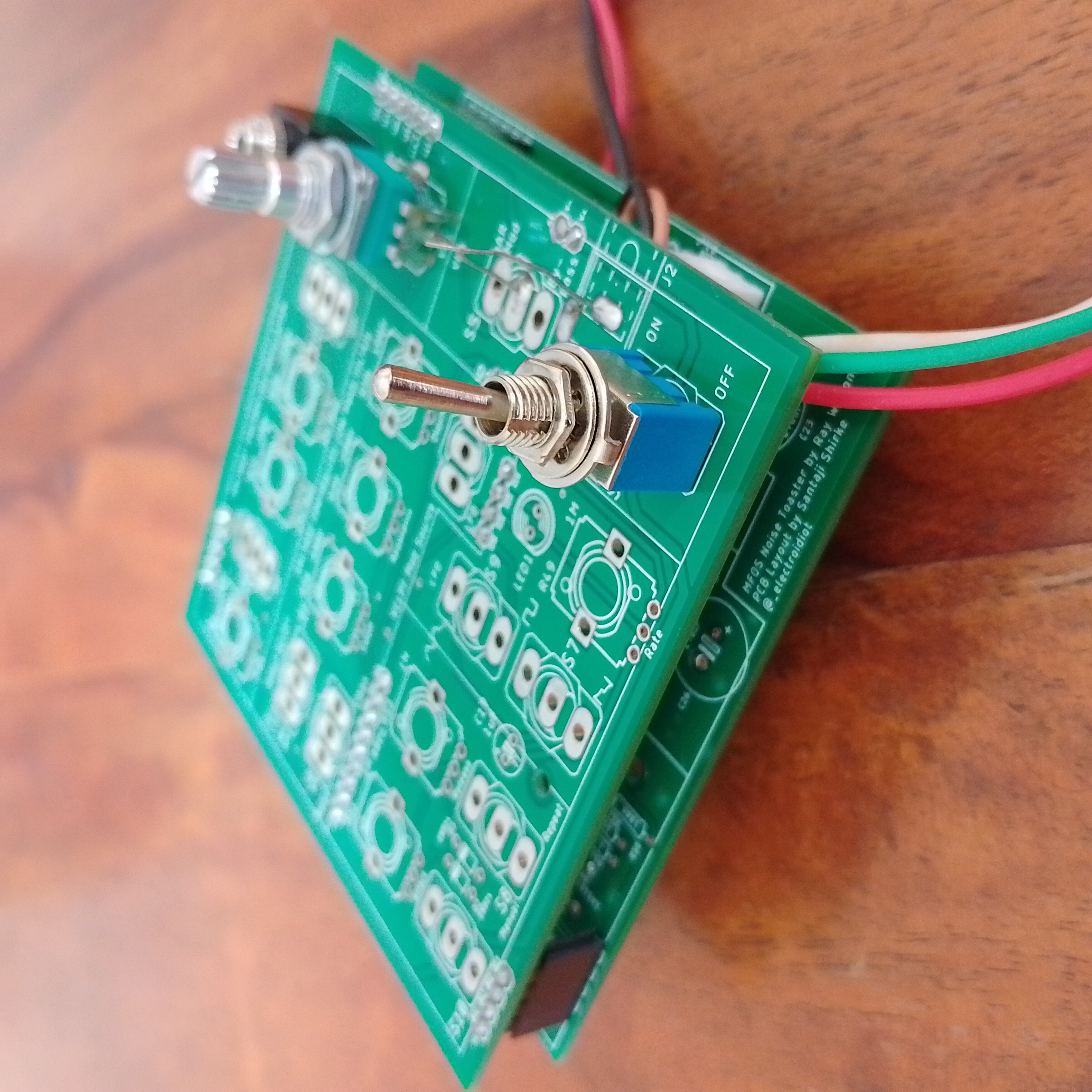
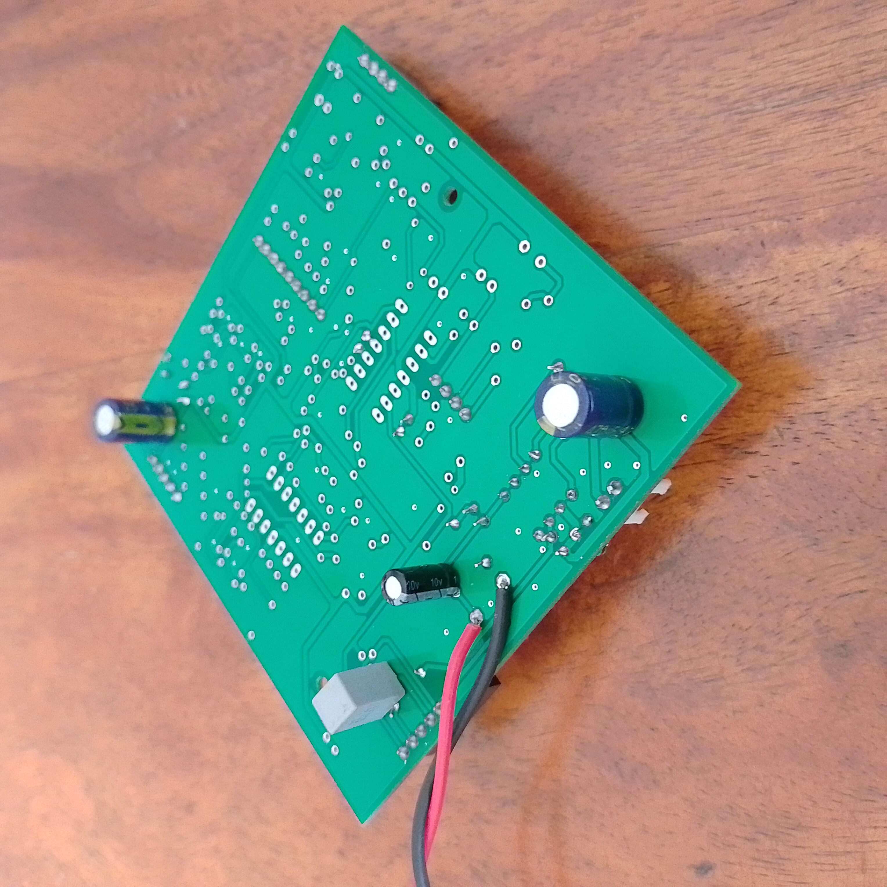
In my two-board sandwiched version of the Noise Toaster, the DC input, volume pot, and line-out jack are located on the top board while the remaining parts of the circuit are on the bottom board. The two boards are connected using single inline headers. To avoid clearance issues, some of the larger capacitors had to be installed on the back of the lower board. Note that as the LM386 is prone to oscillations caused by ground-loops, care had to be taken while designing the PCB to ensure that the audio amplifier stage has the shortest “return path”, separate from any other signal. I implemented a partial “star-ground” scheme that ensures the LM386 circuit has a short and isolated return part to its ground reference (in this case, BN, as this part of the circuit does not use the virtual ground).
With power on the board, and a way to hear our signals, we can now proceed with building the other stages of our synth. To stay updated, make sure to follow @_electroidiot on Instagram.
Recommended Reading
Check out following resources to learn more about the MFOS Noise Toaster:
- Make: Analog Synthesizers by Ray Wilson.
- Official Noise Toaster page on the Music from Outer Space website.
- LM386 Datasheet by Texas Instruments.
- Build a Great Sounding Audio Amplifier (with Bass Boost) from the LM386 on by CircuitBasics.
- LM386 posts on the _electroidiot instagram:
Other Posts in this Series
- Noise Toaster Lo-Fi Synth Build and Analysis: Part 1 – Introduction
- Noise Toaster Lo-Fi Synth Build and Analysis: Part 2 – Power Supply and Audio Power Amplifier
- Noise Toaster Lo-Fi Synth Build and Analysis: Part 3 – CV Mixer, Expo. Converter, and VCO
- Noise Toaster Lo-Fi Synth Build and Analysis: Part 4 – Low Frequency Oscillator (LFO) Circuit Analysis
- Noise Toaster Lo-Fi Synth Build and Analysis: Part 5 – Attack Release Envelope Generator


Leave a Reply