Previously in this multi-part series on the Music from Outer Space Noise Toaster Lo-Fi Analog Synthesizer, we built and analyzed the main Voltage Controlled Oscillator (VCO) circuit. The VCO can be modulated by the Attack Release Envelope Generator (AREG) and the Low Frequency Oscillator (LFO). In this blog post we will build and analyze the Noise Toaster LFO.
What is an LFO on a Synthesizer?
The LFO or Low Frequency Oscillator is a waveform generating circuit that operates between the sub-audio to low audio frequency ranges. An LFO is often used to modulate the synthesizer’s primary oscillator that operates in a higher frequency range. LFOs are also used to modulate other synthesizer circuits such as voltage-controlled filters.
How the Noise Toaster Lo-Fi Synth’s LFO Works

Unlike the VCO, the Noise Toaster LFO circuit is not voltage controlled. This makes the circuit simpler than the VCO circuit we looked at in Part 3.
Comparator/Schmitt Trigger Based Op-Amp Oscillator
Referring to Figure 1, the Noise Toaster’s LFO core is formed by op-amp U2-C set up as a comparator. The comparator’s threshold voltage is set by R55 and R59, to around half of battery positive (BP). However, hysteresis from positive feedback resistor R60 changes this based on the op-amp’s output. This is known as Schmitt Trigger action.
C16 is the timing capacitor. When C16 is discharged, the op-amp’s inverting input is below the threshold voltage. This causes the output at pin 8 to saturate high, and C16 starts charging up slowly through R48 and LFO rate control R49. When C16 charges to above the threshold voltage, the op-amp’s output again goes low and the cycle repeats. The result is a square-wave oscillation at U1-C’s output. The frequency of this oscillation can be adjusted between around 0.75-230Hz by varying LFO rate control R49.
Rate Indicator LED
A cool feature of the Noise Toaster is the LFO rate indicator that blinks in sync with the LFO output. The LED’s cathode is tied to the op-amp’s output and the anode is tied to BP via current limiting resistors R65 and R70. When the op-amp output goes low, the LED is forward biased and turns on until the output goes high again. Charge reservoir capacitor C26 ensures that the current spike caused by the LED does not induce unwanted modulation of the VCO and LFO.
Wave-Shaping with Passive Filters
The Noise Toaster LFO circuit has three selectable outputs that can be used to modulate the VCO and/or the VCF for different effects.
1. Differentiated Square-wave Out
C17 acts like a differentiator or high-pass filter that passes the op-amp output only when it changes suddenly. The resulting spiky looking waveform is known as a differentiated square-wave. Note that C17’s high-pass effect is in conjunction with the load at the LFO output. Thus, the amount of differentiation varies based on how the VCO and VCF CV inputs are set.
Square-wave Out
When S7 is closed, C17 is bypassed, thus the unfiltered square-wave is passed on to the output through S9.
Integrated Square-wave Out
When S9 is flipped to the integrated square-wave position, the op-amp output is routed to the next stage via a low-pass filter formed by R56, and C19. This rounds off the sharp edges of the square-wave and creates a gradually rising and falling waveform. The low-pass filter’s cut-off frequency can be calculated by:
F3db = 1 /((2piRC)) ≅ 8HzEssentially, the low-pass filter cancels out the high frequency harmonics inherent in a square-wave.
Building and Testing the Noise Toaster’s VCO
Noise Toaster PCB
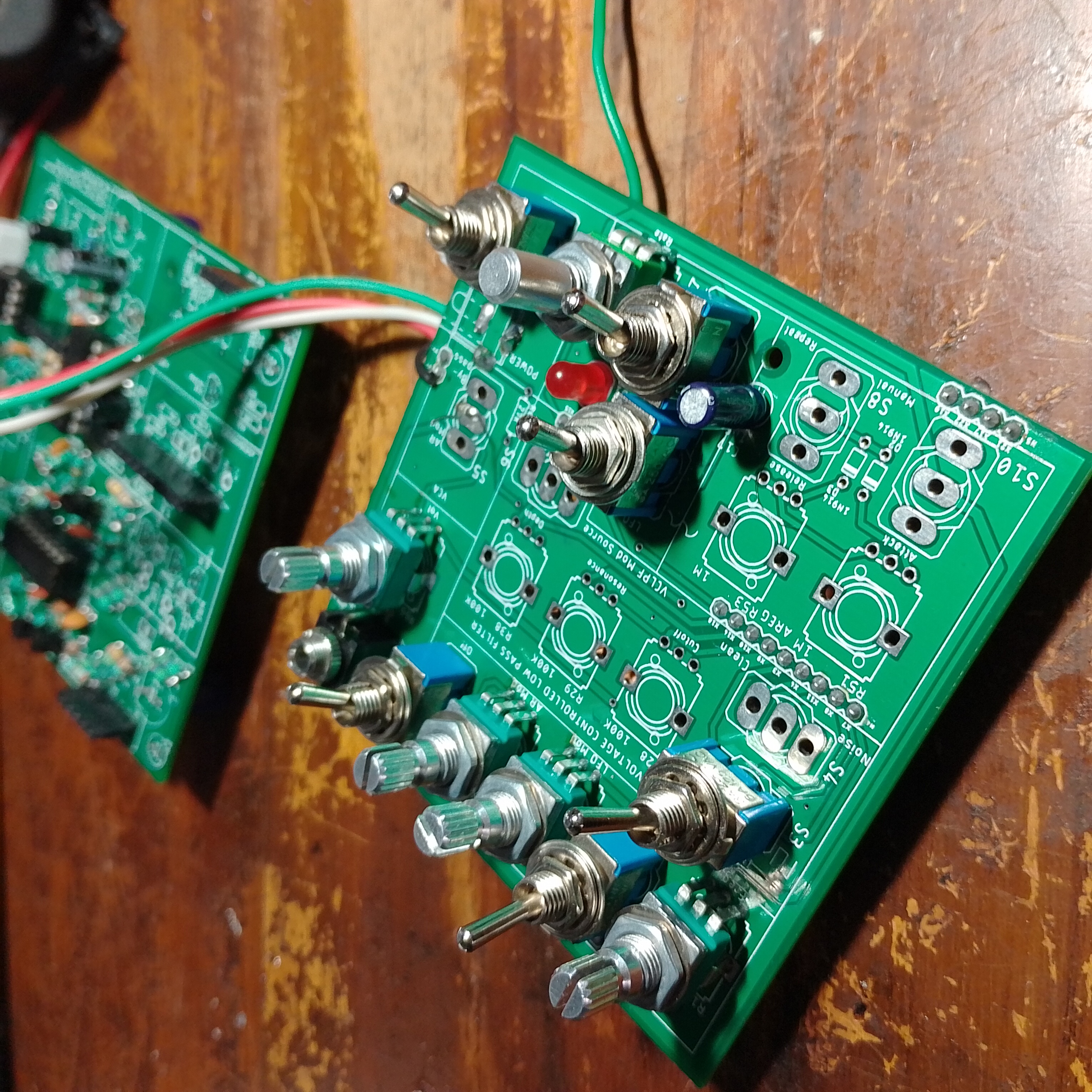

With the LFO assembled and working, we can dynamically change our main VCO’s frequency. Changing the LFO output waveform allows for some neat frequency modulation effects. To learn more about my experimental sandwiched construction PCB design for the Noise Toaster, refer back to Part 1 of the series. If you would like to build your own Noise Toaster, I suggest you get an official MFOS board or kit.

Build Your own Noise Toaster with Official MFOS PCBs and Kits…
In the next post, we’ll build another CV source that can modulate the VCO’s frequency – The Attack Release Envelope Generator. Things are about to get much weirder when we introduce another modulation source!
Follow @_electroidiot on Instagram to stay updated and subscribe to the _electroidiot mailing list below to get notified of new posts!
Get Notified of New Posts, subscribe to the _electroidiot Mailing List.
Recommended Reading
Check out following resources to learn more about the MFOS Noise Toaster:
- Make: Analog Synthesizers by Ray Wilson.
- Official Noise Toaster page on the Music from Outer Space website.
Other Posts in this Series
- Noise Toaster Lo-Fi Synth Build and Analysis: Part 1 – Introduction
- Noise Toaster Lo-Fi Synth Build and Analysis: Part 2 – Power Supply and Audio Power Amplifier
- Noise Toaster Lo-Fi Synth Build and Analysis: Part 3 – CV Mixer, Expo. Converter, and VCO
- Noise Toaster Lo-Fi Synth Build and Analysis: Part 4 – Low Frequency Oscillator (LFO) Circuit Analysis
- Noise Toaster Lo-Fi Synth Build and Analysis: Part 5 – Attack Release Envelope Generator
Join the Conversation
If you notice any mistakes or errors, please feel free to let me know in the comments below.


Leave a Reply